We were about to go on our first trip of the new season when I thought that I had better check if the gas water heater was working, as it had failed less than a year ago when I had to replace the printed circuit board, (PCB), with a similar one I found on eBay.
I’d reached for my motorhome tool kit and the fix seemed to be OK as it worked for all of the six months when we used the motorhome during the summer months. However, the importance of pre-tour checks was highlighted as unfortunately, this time when I turned on the gas heater switch, I was confronted with a solid red warning light which I had never encountered before.
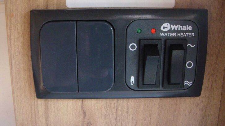
I looked in the owner’s handbook (which came with my motorhome) under the section for the Whale gas and electric storage water heater. Beneath ‘Fault Finding’ it gave a list of possible causes according to the number of flashes of the red light. However, it showed nothing for a solid red light. As the headquarters for Whale were in the next town, I thought I’d drive over and see if they could help.
Luckily, the chap who came out to the motorhome was an expert in these heaters and suggested that the electronics on the PCB needed to be reset. I was a bit confused because the manual made no mention of a reset button, and Whale couldn’t find one on my water heater. To investigate the problem further, I was invited to leave the PCB with them so that they could check it out for me.
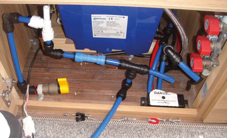
Having previously replaced the PCB, I wasn’t looking forward to removing it again – it meant draining the system, undoing the water pipe connections to the water heater and the water pump, and then removing them as they were blocking access in front of the water heater.
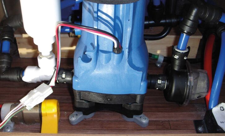
Once the inboard water tank was drained, the plastic pipework was easily disconnected by pushing in the ends of the black pipe connectors with the supplied red plastic disc and then pulling the blue pipe out, while the Whale water pump is simply unscrewed from the floor rubber mounts.
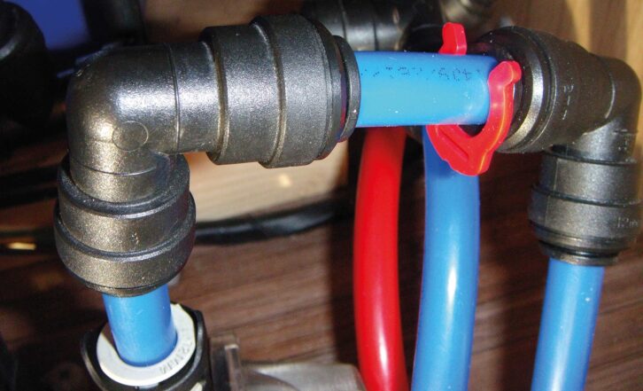
With the pump out, I could unscrew the filter attached to its side and remove the metal gauze to wash away any sediment that had accumulated during the past year.
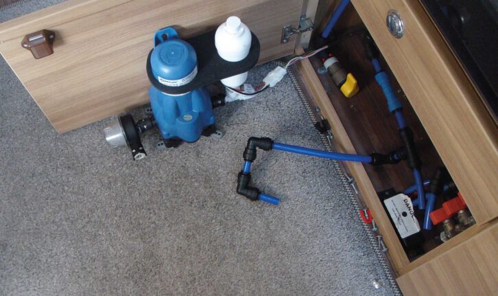
With the pump now out of the way, the blue plastic cover of the front of the water heater was exposed.
It is held on by two screws and when removed, revealing the PCB and the attached wiring.
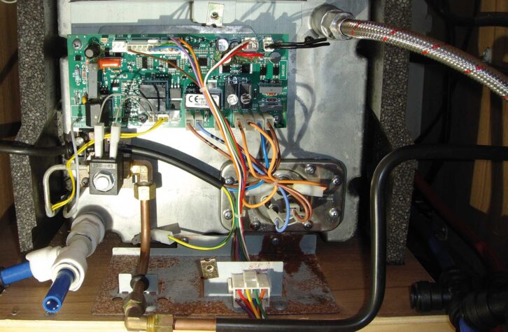
When I did this the first time round I took a photo to remind me where all the connections were before I undid anything, so it would go back together correctly. The connectors are easily unclipped and I found that most will only fit back together one way. There were some that could have been inadvertently misplaced, so I marked these with a felt-pen to be doubly sure.
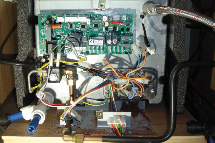
The PCB is fixed to the metal casing at the front of the water heater with four screws and can be removed without touching the gas connection.
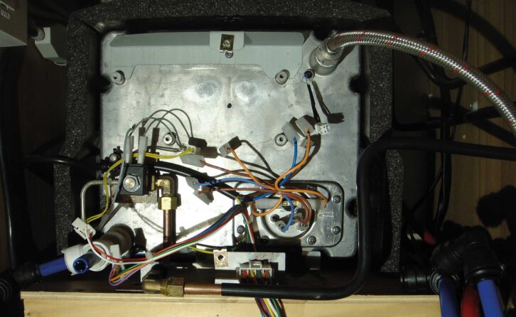
However, I did check if the gas solenoid valve was working by applying a 12V to the two terminals and the clunking on and off showed that it was OK.
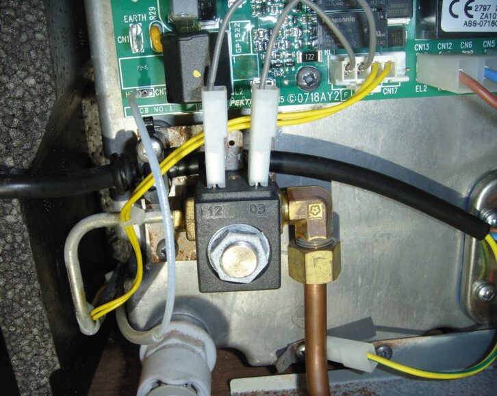
I emailed a photo of this PCB to Whale, who replied saying that the replacement board that I had bought last year was not exactly the same as the one in the photo that I had taken of the original PCB before replacing it.
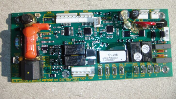
There was only a minor difference: the second PCB had an extra slot CN18 for a reset switch and this was the reason why the control panel was showing the solid red fault light.
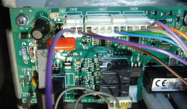
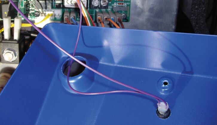
Whale kindly checked the rest of the PCB, confirmed it was working and supplied me with a reset button, which I mounted on the front plastic cover by drilling a 15mm hole.
Reassured that the electronics were working and relieved at not having to fork out for another expensive PCB, I then started reassembling everything back together again.
The wiring for the reset button was now connected to the spare slot in the PCB. Once I was sure that I had all the other electrical connections in the right place, by constantly referring back to the original layout photos, it was a relief to screw on the front cover and see the big red reset button sitting proudly in the centre of the blue panel!
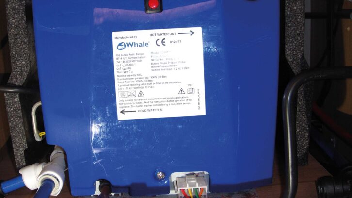
Next job was to reinstall the water pipes, which simply push into the plastic connectors. The first time round I hadn’t pushed them all the way in and as a result several of them had leaked when I turned the water on. This time I made sure they were fully inserted before screwing down the water pump to the floor and then finally connecting it up with the electrical push-on connector.
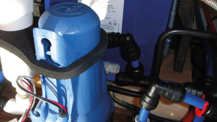
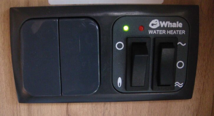
With the inboard water tank filled, the pump was switched on (this time with no leaks); with the gas tanks turned on, it was with some trepidation that I flicked the switch on the control panel. After a heart-stopping few moments I eventually heard to my relief the gas solenoid open with a clunk and then on came a green light to confirm that the gas had ignited and was heating the water.
The lesson I learned from all this was to examine carefully any replacement parts, ensuring they are not only similar, but where possible ensure that both the part numbers match before purchase. I was fortunate that I received assistance from Whale in diagnosing the problem and was provided with a simple solution.
Had I not had that help from the experts at Whale, I would have had to pay out for another expensive new PCB. At long last, with the problem now fixed, we could return to planning for our next motorhome trip!
Don’t miss our guide to how Truma Aventa air conditioning is professionally fitted, as John Sootheran finds out about the process of getting this installed.
Future Publishing Limited, the publisher of Practical Motorhome, provides the information in this article in good faith and makes no representation as to its completeness or accuracy. Individuals carrying out the instructions do so at their own risk and must exercise their independent judgement in determining the appropriateness of the advice to their circumstances. Individuals should take appropriate safety precautions and be aware of the risk of electrocution when dealing with electrical products. To the fullest extent permitted by law, neither Future nor its employees or agents shall have any liability in connection with the use of this information. Double check any warranty is not affected before proceeding.
If you’ve enjoyed reading this article, why not get the latest news, reviews and features delivered direct to your door or inbox every month. Take advantage of our brilliant Practical Motorhome magazine SUBSCRIBERS’ OFFER and SIGN UP TO OUR NEWSLETTER for regular weekly updates on all things motorhome related.